Technology >> Automatic Carton Folding Gluing Machine Working Process
perspective vieW of the flexo folder gluer
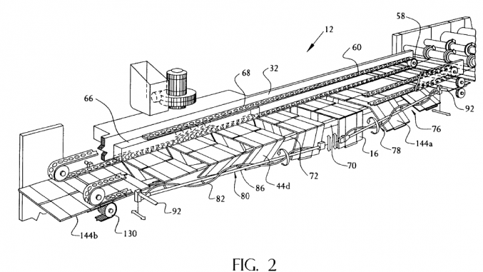
32.upper side rails 34.movable legs 36.folding entrance rail 38.folding exit rail 40.splice plate 66.vacuum box 68.hole 70.folding rail 72.tapered end 76.elongated helix folding assembly 78.first helix folding assembly 80.second helix folding assembly 82.helix contacting member 84.spokes 86.shaft 92.outer actuator 94.inner actuator 130.take-off rollers
Referring to FIGS. 2 and 3A—3C, the folder-gluer 12 has a pair of upper side rails 32 on each side and a plurality of movable legs 34 as the main structural elements. Each upper side rail 32 comprises a folding entrance rail 36 and a folding exit rail 38 which are joined together with a splice plate 40. The side rails 32 and the legs 34 are capable of moving inboard, outboard, and perpendicular to the path of the blank 16 to adjust the width of the folder/gluer 12 in relation to the width of the center panels of the blank 16, as explained below.
Corrugated Carton and Box Blank in Folding Gluing Machine
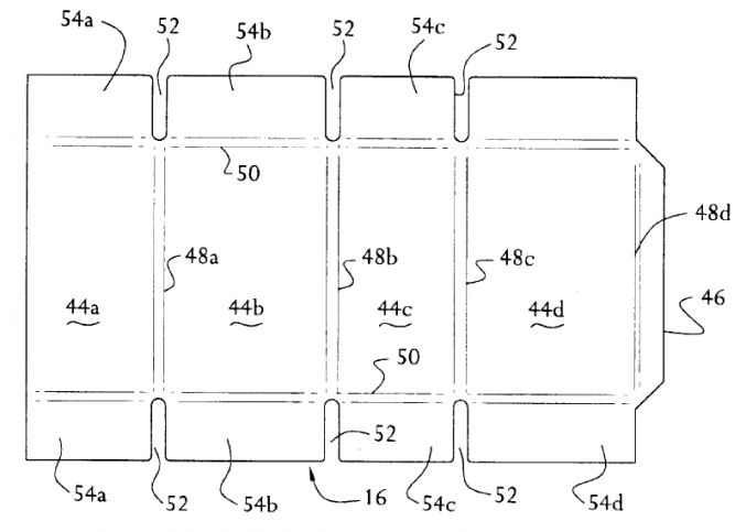
44a,d.outboard panel 44b,c.inboard panel 46.glue tab 48a-d.longitudinal crease 50.score line 52.slot 54a-d.flap
In FIG. 4, the blanks 16 are depicted. Each corrugated blank 16 includes four side-by-side panels 44a—d and a glue tab 46 which are separated by longitudinal creases 48a—a’. Each panel 44a—d includes transverse corrugator score lines 50 and slots 52 which define flaps 54a—a’. The longitudinal creases 48 and the slots 52 are formed upstream of the folder gluer 12 in the creasing slotting unit 20. The glue tab 46 is cut in the rotary die cutter 24.
During the folding operation of the folder/gluer 12, the outboard panel 44a is folded with respect to the inboard panel 44b along the intervening crease 48a and the outboard panel 44d (and associated glue tab 46) is folded with respect to the inboard panel 44c along the intervening crease 48c.
perspective view of the feed end of the folder/gluer
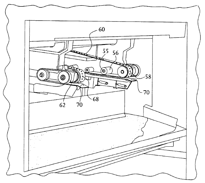
55.bearing 56.upper roller 58.turn around roller 60.conveyor belt 62.pulley 68.hole 70.folding rail 80.helix assembly
Referring to FIGS. 2 and 5, bearings 55 are supported on the inboard side of each upper side rail 32. Rotatably supported on each bearing 55 is an upper roller 56. A plurality of rollers 56 are located along each upper side rail 32, forming a set of upper rollers 56 on each side of the folder/gluer.
Trained on each set of upper rollers 56 and over a turn-around roller 58 is a conveyor belt 60. Each conveyor belt 60 is driven by a pulley 62. The pulleys 62 are driven by the second drive motor (not shown) via an input shaft 30. Each belt 60 has a narrow width (e.g., 4 inches) and a high coefficient of friction surface (e.g., polyurethane rubber or the like) which enables the belt 60 to engage and grip the blanks 16 to move them through the folder/gluer 12. The conveyor belt 60 is continuous and does not require synchronization with the first drive motor or associated units upstream (e.g., the creasing/slotting unit 20, rotary die-cutter unit 24, etc.).
The folder/gluer 12 has a vacuum box 66 located at the exit, or downstream, portion of the folder/gluer 12. Each conveyor belt 60 passes under one of the vacuum boxes 66 and has a plurality of holes 68 through which the vacuum is drawn to hold the blanks 16 during their final folding, as explained below in greater detail.
The folder/gluer 12 has a pair of folding rails 70. Each of the folding rails 70 extends from the entrance of the folder/ gluer 12 adjacent to the rotary die-cutter 24 for approximately three-quarters of the length of the folder/gluer 12, i.e., approximately to the mid-point of the second helix assembly 80. The inner panels 44b and 44c of the blanks 16 pass over the folding rails 70. The folding rails 70 are inboardly and outboardly adjustable such that the distance between their outer edges is equal to the combined width of the two inner panels 44b and 44c of the blank 16. The folding rails 70 support the blanks 16 until the blanks 16 reach the portion of the folder/gluer 12 where the vacuum box 66 is located.
Each folding rail 70 has a tapered end 72, as best seen in FIG. 3A. The tapered end 72 terminates sufficiently prior to where the folding process is completed so it does not become trapped inside the completed fold of the blank 16. Each tapered end 72 is positioned to underlie one of the conveyor belts 60. The folding rails 70, including the tapered ends 72, function to press the blanks 16 passing thereover against the adjacent conveyor belt 60 to assure good grip ping contact between the belt 60 and the blanks 16. In the portion where there is no folding rail 70, the vacuum created by the vacuum box 66 ensures that the blank 16 is in good gripping contact with the conveyor belt 60 for the final folding stage.
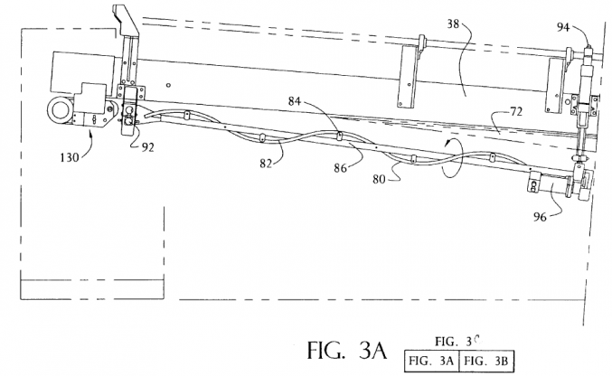
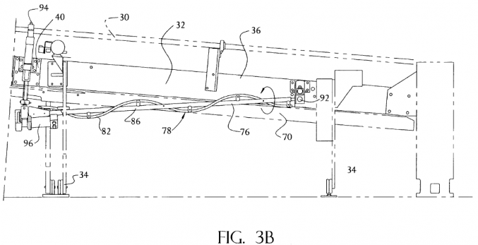
Referring to FIGS. 2 and 3, the folder-gluer 12 has a plurality of elongated helix folding assemblies 76 one located on the operator side and the other located on the drive side of the folder/gluer 12. The drive side helix assemblies are only partially seen in FIG. 2. Each helix assembly 76 comprises a first helix folding assembly 78 and a second helix folding assembly 80. The first and second helix folding assemblies 78 and 80 on the drive side are generally symmetric about the board travel line to those shown on the operator side and rotate in a clockwise direction. The first and second helix folding assemblies 78 and 80 each have a shaft 86, a plurality of spokes 84 extending from the shaft 86, and a helix blank contacting member 82 supported by the spokes 84. The shaft 86 extends coaxially with the longitudinal axis of the contacting member 82. Preferably, each helix blank contacting member 82 forms a cylindrical helix winding around the shaft 86 which has preselected radius and pitch.
The “radius” is the radius of the enveloping cylinder. The “pitch” is the axial distance (length of axis) needed for the helix to wind around its axis exactly once. The helix blank contacting members 82 are preferably constructed to have a low friction surface (e.g., of nylon).
The embodiment described herein depicts a folder/gluer in which the outboard panels of the blanks are folded downward and then upward under the center portion of the blank. This is commonly referred to as a “down folder,” that is, the second panel is supported from above. U.S. Pat. No. 4,254,692 entitled “Helix Folder for Paperboard Blanks” describes an apparatus which uses a single set of elongated helix folding means for folding the outboard panels of the blanks from an upward position, via a stationary rail, downwardly over the center portion of the blank. This is commonly referred to as an “up folder,” that is, the second panel is supported from below. The choice between folding under as opposed to folding over or over generally depends on whether printing has been done on the topside or the bottomside of the board. For example, in the instant invention the printing would be done on the topside. U.S. Pat. No. 4,254,692 is hereby incorporated herein by reference.